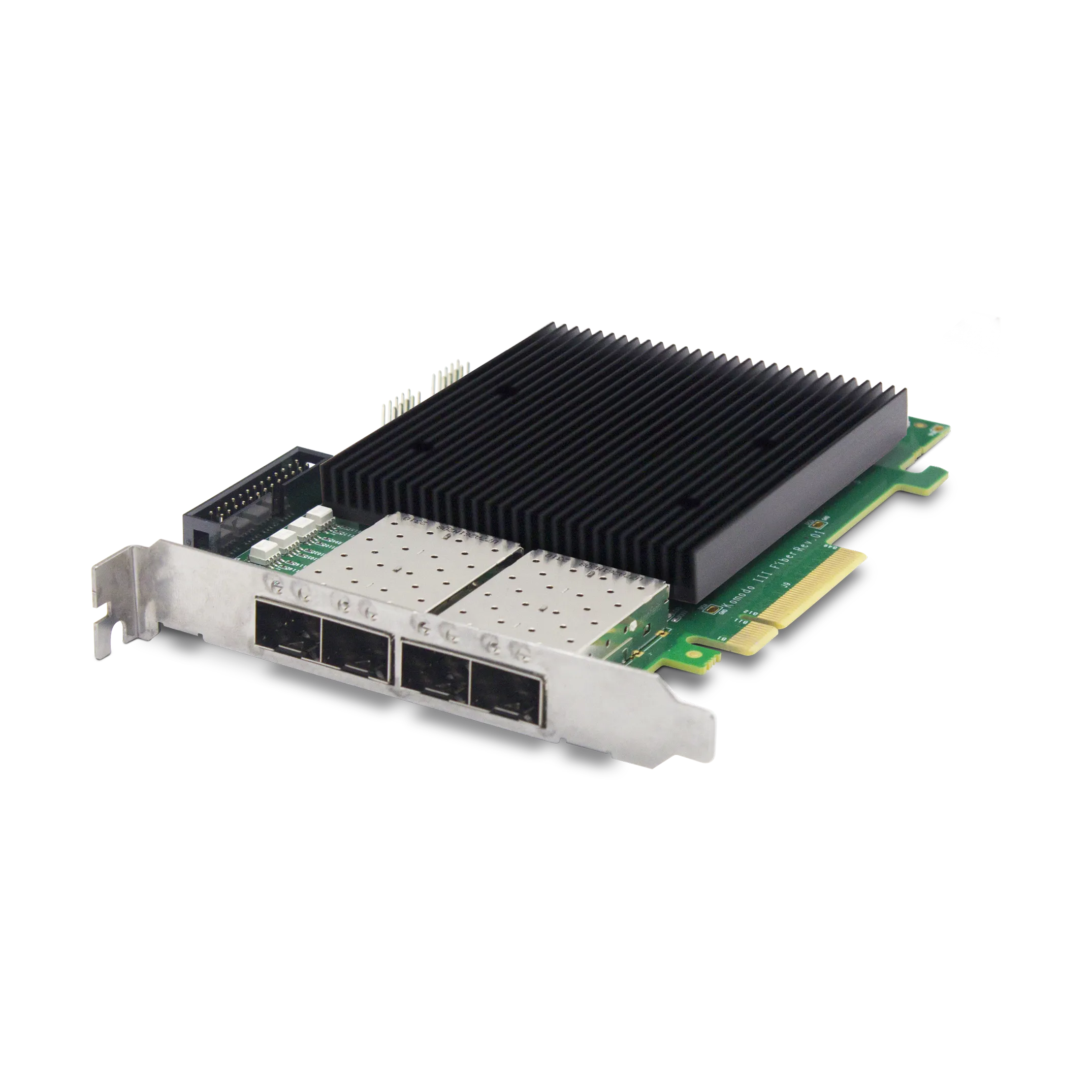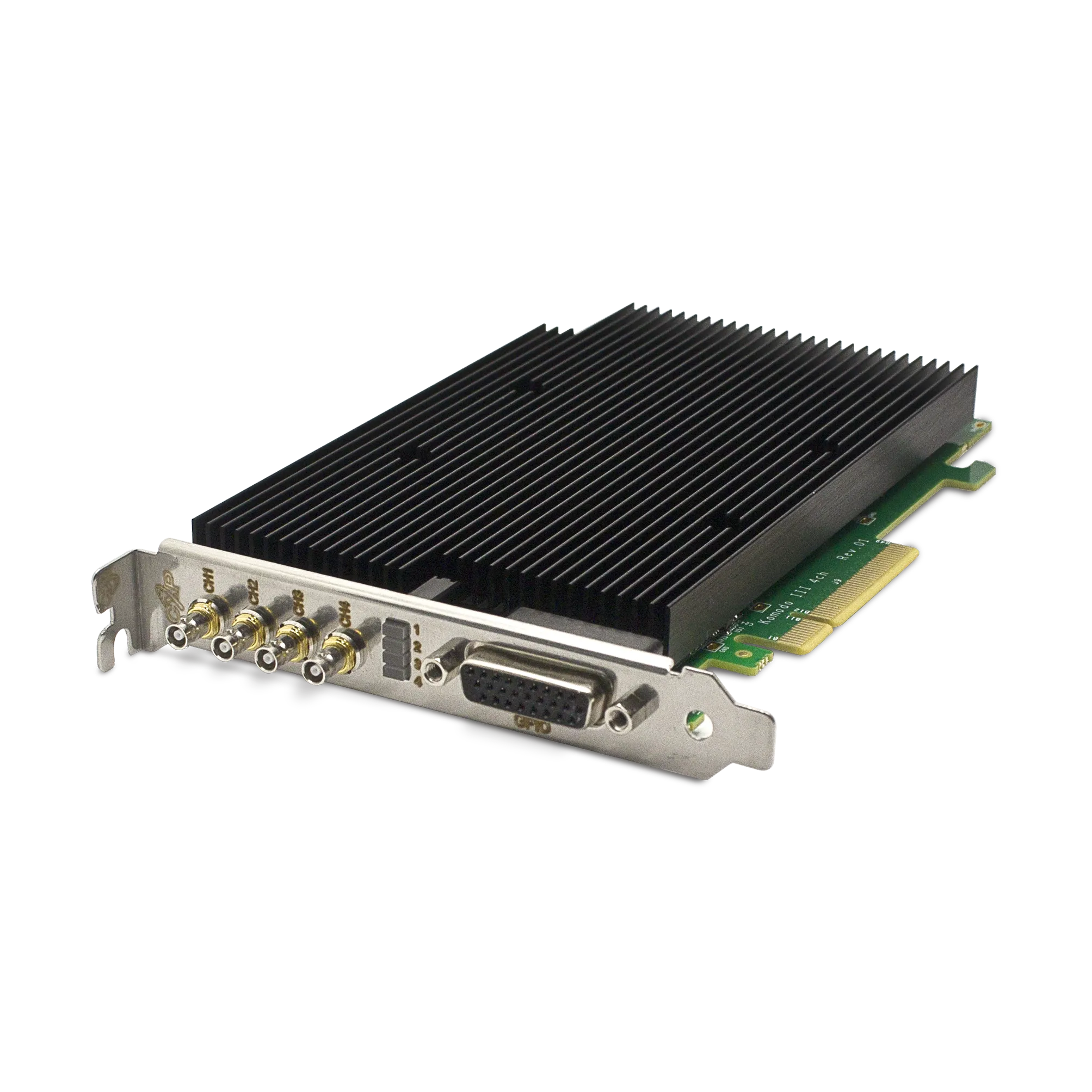
A CoaXPress over Fiber frame grabber must match the transmitting device at the protocol, link and optical levels. A fiber connector or transceiver form factor alone does not establish compatibility. Start with the complete path from transmitter through modules and fiber to the receiver, then verify the host can accept the combined stream.

Record the protocol and the rate of every link
The Komodo III Quad CoaXPress over Fiber product page lists four SFP+ ports, up to 10.3125 Gb/s per link, PCIe 3.0 ×8 and a 4 GB onboard buffer. That configuration should not be described as interchangeable with every 100 Gb/s optical acquisition system. A family name such as CoaXPress over Fiber can cover different physical implementations.
| Compatibility layer | Details to confirm |
|---|---|
| Protocol | CoaXPress over Fiber support at both ends; required versions and device configuration. |
| Link mapping | Active link count, per-link rate and ordering for a multi-link stream. |
| Transceivers | Supported module types, wavelength, electrical interface and vendor compatibility guidance. |
| Fiber path | Single-mode or multimode fiber, connector type, length and permitted loss. |
| Host | Sustained DMA rate, negotiated PCIe width and aggregate processing load. |
A mechanically compatible optical module may still use an unsuitable wavelength, fiber type or signaling configuration. Confirm the supported combination with the equipment documentation instead of substituting modules based on appearance.
Build an optical-loss budget
As a hypothetical example, a transmitter with a minimum output of −3 dBm and a receiver sensitivity of −11 dBm has an 8 dB gross budget. If the fiber, connectors and splices together account for 5 dB, the remaining allowance is 3 dB. This arithmetic is an example, not a specification for KAYA hardware or a recommendation for a particular optic.
Use the actual module data for minimum transmit power, receive sensitivity and maximum receiver input. Include aging, temperature and installation allowances appropriate to the project. Also check maximum receiver power on short links; a low-loss path is not automatically valid for every optical pair. Have the selected combination reviewed when documentation does not clearly cover it.
Keep image payload and physical line rate separate
The sum of the physical link rates is not the same as usable image bytes per second. Encoding, protocol overhead, packing and the delivered pixel format affect the available payload. An onboard buffer can absorb temporary differences between input and host service but cannot sustain a continuously overloaded PCIe or processing path.
Use the frame-grabber bandwidth worksheet for the host side and confirm the permitted payload with the transmitter and receiver configuration. Treat link grouping as part of commissioning: an incorrectly mapped multi-link stream can fail even when individual links appear active.
Plan power and commissioning separately
Optical fiber does not carry electrical camera power. Provide the remote device with its documented supply arrangement, and include converter power if the design uses a coax-to-fiber conversion stage. Check grounding and installation requirements for powered equipment at both ends.
- Record the module part numbers, fiber type, path length and link mapping.
- Inspect and clean optical connections using the appropriate procedure.
- Check receiver status and available error counters at the intended acquisition rate.
- Run the complete stream and processing workload long enough to expose intermittent errors.
- Document a known-good configuration for future cable or module replacement.
KAYA’s stream statistics guide covers error checks, including fiber-link information. If errors appear, use the acquisition fault-isolation sequence to distinguish optical transport from host-buffer problems.
Contact KAYA Instruments with the transmitter, module part numbers, fiber route, link count and image rate to confirm an appropriate optical acquisition configuration.