Multi-camera synchronization starts with a definition: do the exposures need to begin together, overlap for a specified duration, or simply belong to the same acquisition cycle? A frame grabber can distribute and monitor trigger events, but simultaneous arrival in host memory is not evidence that two images were exposed simultaneously.

Define the timing requirement before wiring
Write down the maximum allowable exposure-start difference, exposure duration, acquisition period and acceptable missed-trigger behavior. State whether timing is measured at the trigger connector, the camera exposure-active output or in metadata. Sensor behavior and camera response add uncertainty after the electrical trigger, so a precise trigger source alone does not establish optical synchronization accuracy.
| Timing point | What it tells you |
|---|---|
| Trigger edge | When the acquisition request reached a measured electrical point. |
| Exposure-active signal | A camera-reported exposure interval; interpretation depends on that camera. |
| Frame timestamp | The event associated with a device timestamp; verify its clock and definition. |
| Host buffer arrival | When software can use the image, after readout and transfer. |
Choose one deliberate trigger architecture
A common design uses one timing master and distributes its output to the participating devices. Another uses a frame-grabber timer as the master and compatible GPIO connections to additional grabbers. KAYA’s frame-grabber synchronization guide describes master and slave configuration. Use the pinout, electrical levels and settings for the exact board and firmware revision; connector shape does not establish signal compatibility.
Also distinguish a trigger that controls camera acquisition from a trigger that controls receiver behavior. KAYA’s trigger documentation treats these as different mechanisms. Configure the intended path explicitly instead of enabling multiple trigger modes experimentally and assuming their effects combine.
Build a timing budget
For an illustrative 200 Hz acquisition cycle, the period is 1,000,000 ÷ 200 = 5,000 microseconds. A 1,000-microsecond exposure occupies part of that cycle, but the remaining 4,000 microseconds is not automatically available for every other operation: readout, overlap support and trigger acceptance depend on the camera configuration. Validate the permitted cycle using device documentation and measurements.
For skew, budget the source, output circuitry, distribution path and device response. Measure the complete path at the relevant endpoints. Do not use a timestamp resolution or GPIO timer increment as a claim of achieved synchronization accuracy. Resolution describes a numerical step; accuracy requires a reference and an error measurement.
Verify matching images in software
- Associate each image with a trigger sequence or frame identifier where supported. Detect gaps explicitly.
- Queue enough buffers for all participating streams before acquisition starts.
- Test startup, stopping, trigger bursts and a disconnected or unavailable stream. Define how the application handles an incomplete set.
- Measure host-arrival variation separately from exposure skew. Independent DMA scheduling can change arrival order.
- Repeat the timing test while processing and recording are active, and save the test conditions with the results.
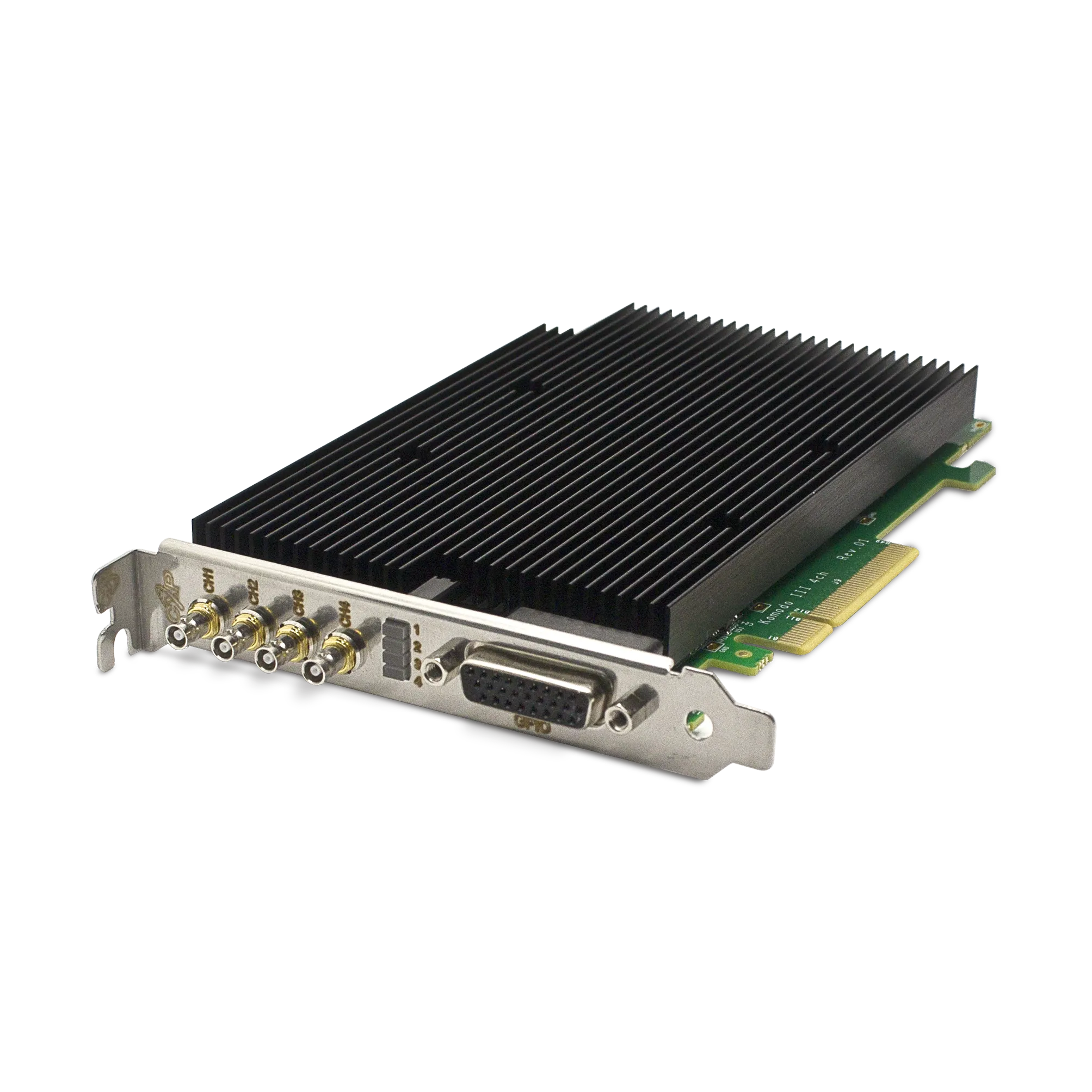
The Komodo III Quad CoaXPress 12G supports multiple acquisition links and synchronization functions. Its suitability still depends on the required input/output arrangement and measured timing performance. Review aggregate PCIe bandwidth as part of the same design; synchronized bursts can stress a host even when average rates appear manageable.
Can software start commands synchronize exposures?
A software start command can coordinate a workflow, but operating-system scheduling and command delivery introduce variable delay. When the requirement is a defined relationship between exposures, use a supported hardware timing path and verify it against that requirement.
Discuss the synchronization design with KAYA Instruments using a timing diagram, stream count, electrical interface requirements and the maximum permitted skew. Those details make hardware selection and acceptance testing concrete.