A line-scan frame grabber must keep spatial sampling, trigger timing and continuous data delivery aligned. Start with conveyor motion and required sampling distance, then calculate the line rate and host-buffer rate. Choosing a board from a headline frames-per-second figure can miss the constraints that matter in a continuous inspection system.

Convert motion into a required line rate
If the object moves at velocity v and the desired distance between lines is d, the required line rate is v ÷ d. Keep the units consistent. At 2 metres per second with a 0.05 mm sampling interval, the required rate is 2,000 mm/s ÷ 0.05 mm = 40,000 lines per second. The interval between lines is 25 microseconds.
This is a sampling calculation, not a statement about any camera’s maximum speed. The selected camera must accept the trigger rate with the chosen exposure and readout configuration. At variable conveyor speed, an encoder-based trigger can tie acquisition to motion. Basler’s trigger application documentation describes encoder-driven line-scan arrangements.
Match encoder counts to physical distance
Record the effective travel per encoder count after the configured decoding mode, mechanical ratio and any trigger division. A quoted pulses-per-revolution value is insufficient if the system uses a different edge-counting convention. Check direction changes, slip, vibration and missing encoder events. Decide whether reverse motion should produce images, pause acquisition or be handled by a supported compensation mode.
Test the physical sampling interval with a known target. A correct arithmetic ratio does not compensate for a slipping measuring wheel or an incorrectly configured trigger input. Confirm electrical levels and use the board-specific GPIO documentation before connecting the encoder.
Calculate the continuous host load
For an 8,192-pixel line at 40,000 lines per second, a 16-bit host buffer requires 8,192 × 40,000 × 2 = 655,360,000 bytes per second, or 655.36 MB/s before padding and metadata. Packed 12-bit input would contain 491.52 MB/s of image samples. The difference matters if unpacking occurs on the grabber before DMA.
Apply the same calculation to every stream and compare it with the actual link and host connection. The PCIe bandwidth guide explains why transport packing and host layout require separate budgets.
Choose lines per buffer from latency and processing needs
| Lines per buffer at 40,000 lines/s | Time to collect those lines | Payload at 8,192 pixels × 2 bytes |
|---|---|---|
| 256 | 6.4 ms | 4 MiB |
| 1,024 | 25.6 ms | 16 MiB |
| 4,096 | 102.4 ms | 64 MiB |
These are calculated accumulation times and payload sizes, excluding other delays. Larger groups reduce the number of buffer-completion events but postpone access to a completed group. They also increase the memory tied up by each queued buffer. Choose a grouping that fits the inspection region and response-time requirement, then measure the complete processing latency.
KAYA’s acquisition FAQ describes the SegmentsPerBuffer setting for grouping lines or frames. Check the installed SDK documentation for its exact behavior and when it can be set. Do not change grouping without updating the application’s expected buffer dimensions and ownership rules.
Commission the system as a continuous pipeline
- Test maximum conveyor speed and acceleration, not only a steady low-speed run.
- Check line continuity across buffer boundaries with a known pattern.
- Measure queue depth while inspection and recording run together.
- Define object-start and object-end handling separately from individual line triggers.
- Verify the smallest defect representation and reject timing against actual motion.
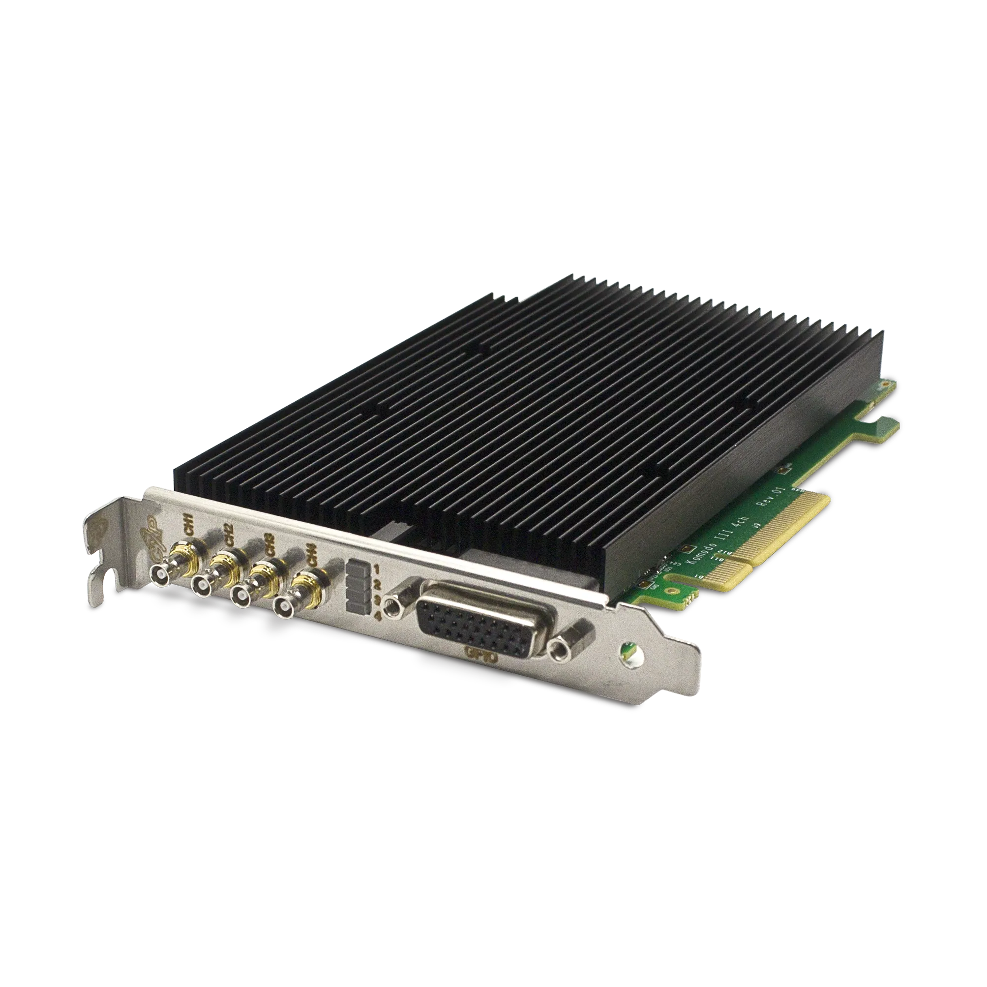
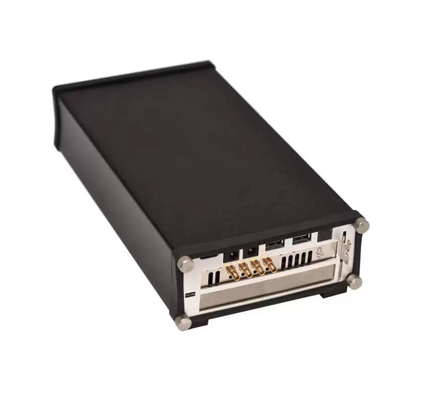
The Komodo III Quad CoaXPress 12G supports line-scan acquisition and encoder-related control functions. Send KAYA Instruments the line width, sampling interval, speed range and processing deadline to review an acquisition configuration for your machine.