| Single Camera Link Topology: |
Key Features:
Ordering Codes:
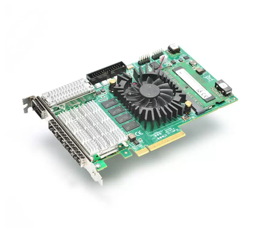
KY-FXCL-II
| General | |
|---|---|
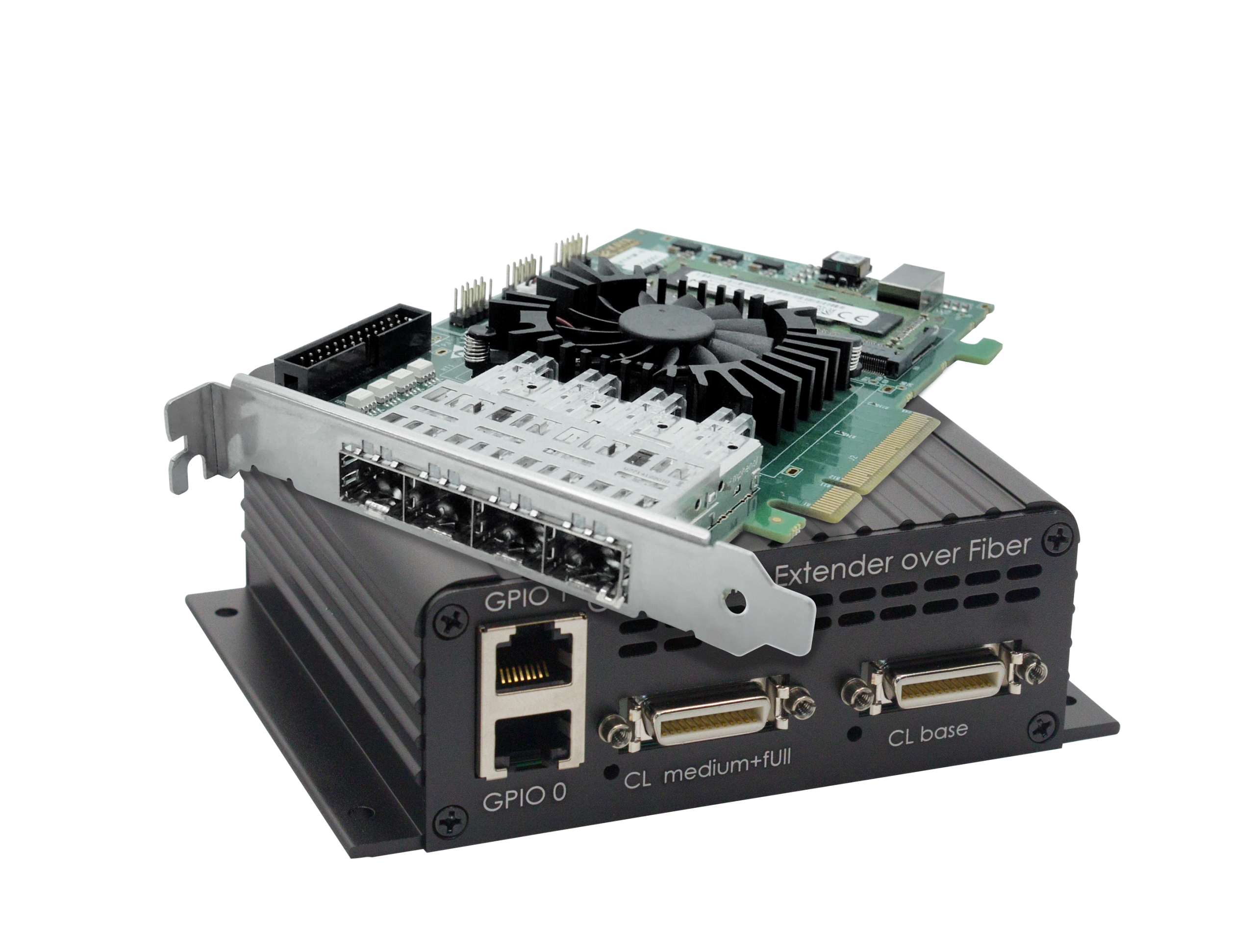
| Form factor | PCI Express card + remote device |
| Format | Standard profile, half-length, 8-lane PCI Express card |
| Cooling method | Air cooling, fan-cooled heatsink (Optional passive heatsink) |
| Mounting | For insertion in a standard height, 8-lane or higher, PCI Express card slot |
| Dimensions | Frame Grabber: 167.65 mm x 111.15 mm (6.6” x 4.4”) Remote device: 133 x 103 x 43 mm (5.23” x 4.05” x 1.7”) |
| Weight | Frame grabber: 183 g (6.5 oz) Remote device: 348 g (12,275 oz) |
| Host bus | |
| Standard | PCI Express 3.0 |
| Link width | 8 lanes 1, 2 or 4 lanes with reduced performance |
| Link speed | 8.0 GT/s (PCIe 3.0) 5.0 GT/s (PCIe 2.0) with reduced performance |
| Maximum payload size | 2,048 bytes |
| DMA | 64-bit addressing support Scatter gather support Physical address support (GPU transfers) |
| Peak delivery bandwidth | 7,877 MB/s |
| Effective delivery bandwidth | 6,695 MB/s (Host PC dependent) |
| Power consumption | Frame grabber: 16.8 W Remote device: 10.8 W |
| Camera / video inputs | |
| Interface standard(s) | Camera Link compatible v2.0 |
| Status LEDs | 1 bicolor status LED per connector 4 System status LEDs |
| Number of cameras | Up to 4 |
| Synchronization between cameras | Yes |
| Line-scan cameras supported | Yes |
| Maximum aggregated camera data transfer rate | 63.8 Gbit/s |
| Maximum stream packet size | 8,192 bytes |
| Camera types | Area-scan cameras: Gray-scale and color (RGB and Bayer CFA) Line-scan cameras: Gray-scale and color RGB |
| General Purpose Inputs and Outputs | |
| Number of lines | 20 I/O lines: 2 differential inputs 2 differential outputs 4 single-ended TTL inputs/outputs 4 single-ended LVTTL inputs/outputs 4 opto-isolated inputs 4 opto-isolated outputs |
| Usage | Any System I/O input lines can be connected to any I/O output line Any I/O input line can be used to decode A/B and Z signals of a motion encoder Any I/O input line can generate any trigger event Any I/O input line can trigger a timer |
| Electrical specifications | Differential lines – LVDS compatible TTL lines – 5V TTL compliant LVTTL lines – 3.3V LVTTL compliant Isolated lines – opto isolated lines with voltage range up to 30 V |
| Filter control | Glitch removal filter for Encoders and Triggers Configurable filter time between 0 μs and 34 ms Filter time resolution of 8 ns |
| Polarity control | Yes |
| Encoders | 4 quadrature encoders with A/B and Z inputs 32-bit position counter Forward and backward counting Position trigger support Noise filtering |
| Timers | 4 general-purpose timers Configurable delay and duration 32-bit accumulator |
| Event reporting | 64-bit system timestamp event reporting Each I/O line can generate an event on a configurable edge Each Timer can generate an event Each encoder can generate an event |
| Frame Grabber synchronization | |
| Synchronization | Precise area and line-scan cameras synchronization across different frame grabbers |
| Area-scan camera control | |
| Trigger | Precise control of asynchronous reset cameras, with exposure control Support of camera exposure/readout overlap Support of triggering from encoder or timer Support of external hardware trigger, with optional delay, filtering and trigger decimation |
| Strobe | Accurate control of the strobe position for strobe light sources Support of early and late strobe pulses |
| Line-scan camera control | |
| Scan/page trigger | Precise control of start-of-scan and end-of-scan triggers Support of external hardware trigger, with optional delay and filtering Support of triggering from an encoder Support of infinite acquisition, without missing lines |
| Line trigger | Support for quadrature motion encoders, with programmable filters, selection of acquisition direction and backward motion compensation |
| Line strobe | Accurate control of the strobe position for strobe light sources |
| On-board processing | |
| On-board memory | 4 GByte DDR4 |
| Bayer de-mosaic | Full 16-bit resolution Bilinear 3×3 Bilinear 3×2 for linescan with gradient correction |
| Color transformation | Full 16-bit resolution 18bit coefficients table: Color space conversion Gain and Offset |
| Decimation | Line skip |
| Additional features | Unpacking of 10-/12-/14-bit to 16-bit LSB aligned Frame timestamp 64-bit with 8 ns precision |
| Data stream statistics | Measurement of frame rate, CRC errors, received/dropped frames, received/dropped packets, test packets |
| Event signaling and counting | The application software can be notified of various events: Newly acquired buffers Camera and Illumination control events I/O events Timer events Encoder events |
| Software | |
| Host PC operating system | Windows 10 64-bit, Windows 11 64-bit Signed and certified kernel driver Source code Linux kernel driver (tested Ubuntu 18.04, 20.04, 22.04) Nvidia Xavier AGX & Orin AGX support |
| GenCam | Support of GenCam 3.2 Full camera and Frame Grabber parameters configuration |
| Buffer management | Circular buffer support Accumulation of several frames/lines to single buffer to reduce CPU load Flexible buffer queuing DMA Buffer filling directly to system memory |
| GUI | Supported for Windows and Linux OS Multi camera display and configuration Image/video recording and playback |
| Debugging capabilities | Event logging Statistics counters |
| APIs | GenCam, GenTL producer libraries, ANSI C, Python, .NET bindings x86 64 dynamic library Plug-ins for Matlab, HALCON, Cognex, Labview Practical examples and documentation included |
| Environmental conditions | |
| Operating ambient air temperature | -40 °C to +70 °C (-40 °F to +158 °F) |
| Operating ambient air humidity | 10% to 90% RH non-condensing |
| Storage ambient air temperature | -40 °C to +70 °C (-40 °F to +158 °F) |
| Storage ambient air humidity | 10% to 90% RH non-condensing |
| Certifications | |
| Electromagnetic – EMC standards | European Council EMC Directive 2004/108/EC FCC rule 47 CFR 15 |
| EMC – emission | EN 55022:2010 Class B FCC 47 Part 15 Class B |
| EMC – immunity | EN 55024:2010 Class B EN 61000-4-3 EN 61000-4-4 EN 61000-4-6 |
| Flammability | PCB compliant with UL 94 V-0 |
| RoHS | Compliant with EU Directive 2011/65/EU (ROHS2) |
| REACH | Compliant with EU Regulation No 1907/2006 |
| WEEE | Must be disposed of separately from normal household waste and recycled according to local regulations |
| Ordering information | |
| FXCL II Acquisition system | KY-FXCL-II |
| Camera Link compatible Range Extender over Fiber – Device unit | KY-CL2F-D |
| Komodo II CLHS compatible Frame Grabber | KY-FGF-II-CLHS |
| SFP+ single-mode module, 10 km | KY-SFP-10GLR-31 |
| SFP+ multi-mode module, 300 m | KY-SFP-10GSR-85 |
| SFP+ single-mode bidirectional module | KY-SFP-BD-10G-10 |
| Fiber cable | KY-FCA-X |
| Camera Link cable | KY-CCL-X |
| Power supply 12 V, 60 W | KY_PWR12_60 |
Example System Block Diagram
The Camera Link Range Extender over Fiber supports multiple modes of configuration and system topology. Few of these are presented in following diagrams.
| Single Camera Link Topology: |

Dual Camera Topology

Quad Camera Topology


FXP III Acquisition system

CoaXPress Range Extender over Fiber (SFP+)
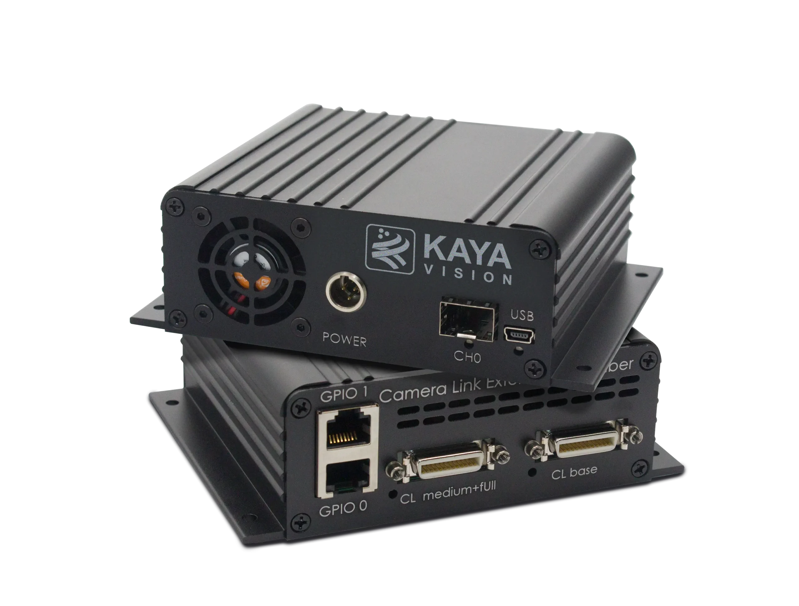
Camera Link Range Extender over Fiber
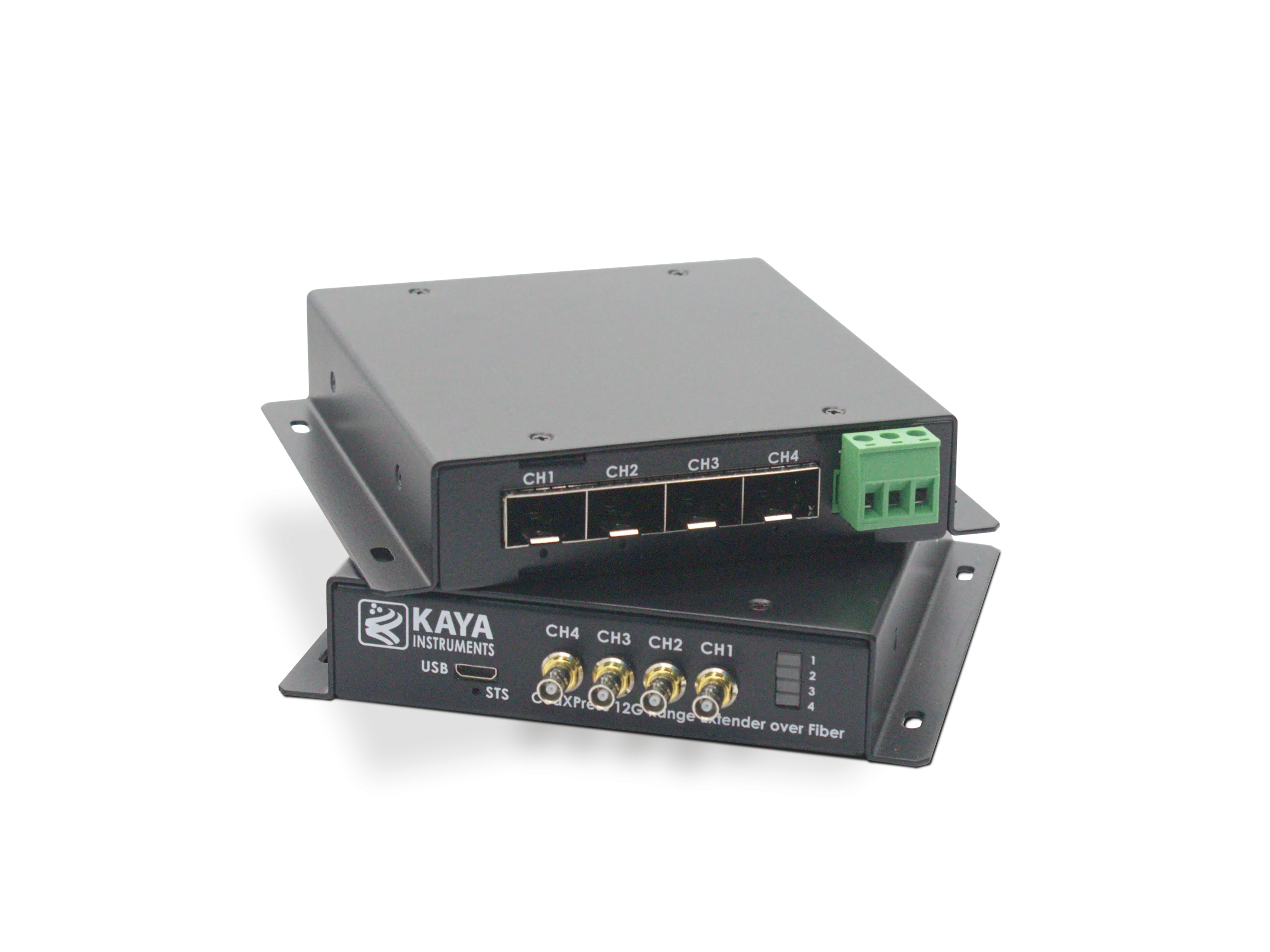
CoaXPress v2.1 Range Extender over Fiber (SFP+)
CoaXPress Range Extender over Coax