| Single Camera Link Topology: |

Key Features:
Ordering Codes:
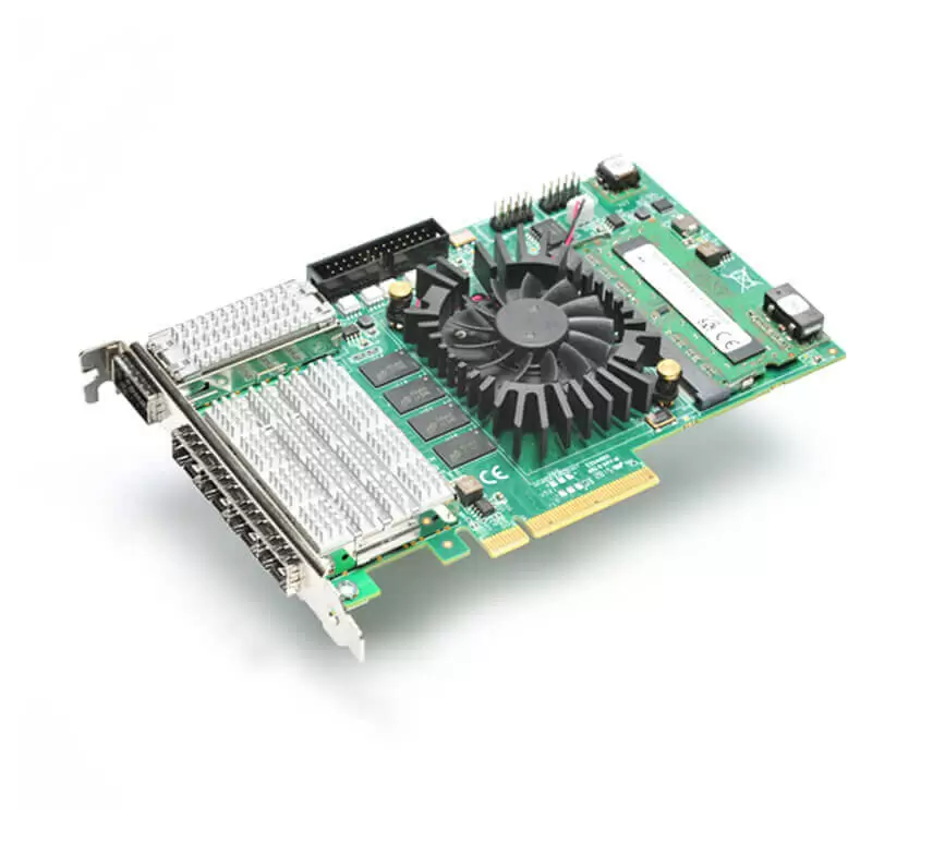
KY-FXCL-III
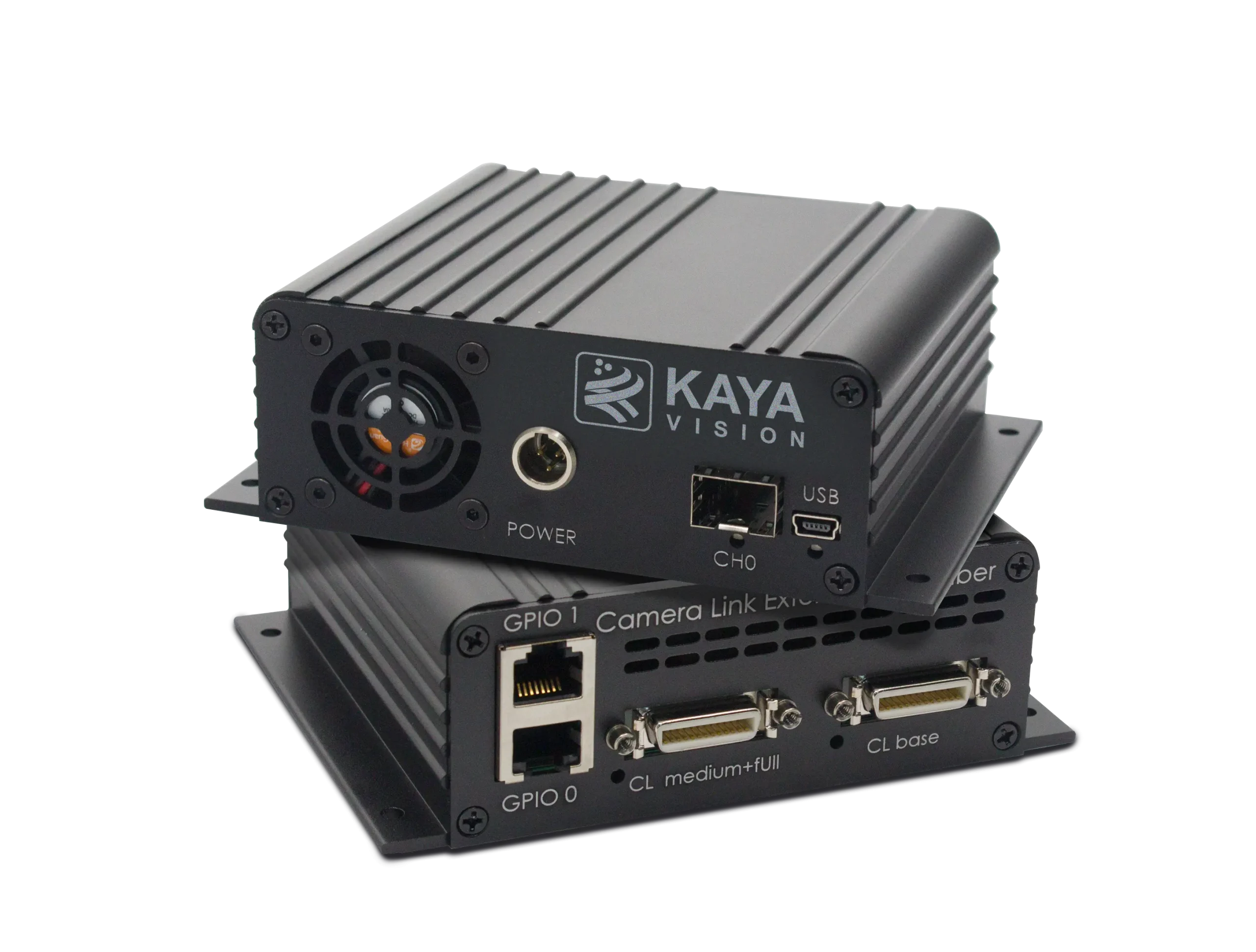
The FXCL III Acquisition system is the industry most advanced Camera Link compatible image acquisition system without range limitations. The system uses fiber optic cables to provide high resolution image acquisition interface for distances up to 80 km in single-mode and up to 300 m in multi- mode, while each Camera Link Full interface translated to single fiber cable. The FXCL III Acquisition system is capable of receiving video streams from Camera Link Full camera while such interface supports standard Camera Link bitrates up to 100 MHz. This system is ideally suited for industrial, defense and aerospace Machine Vision Systems and applications. The system consists of Komodo III CLHS compatible frame grabber and CameraLink to CLHS converter unit. The remote unit converts CameraLink interface to fiber optic interface. The FXCL III system uses a high performance flow through DMA to transmit video streams to computer memory through PCIe interface with minimal latency. This product also provides GPIO for machine control signals, such as triggers, shaft encoders, exposure control and general I/O, which can be control aside video stream acquisition.
| General | |
|---|---|
| Form factor | PCI Express card + remote device |
| Format | Standard profile, half-length, 8-lane PCI Express card |
| Cooling method | Air cooling, fan-cooled heatsink (Optional passive heatsink) |
| Mounting | For insertion in a standard height, 8-lane or higher, PCI Express card slot |
| Dimensions | Frame Grabber: 167.65 mm x 111.15 mm (6.6” x 4.4”) Remote device: 133 x 103 x 43 mm (5.23” x 4.05” x 1.7”) |
| Weight | Frame grabber: 250 g (8.8 oz) Remote device: 348 g (12,275 oz) |
| Host bus | |
| Standard | PCI Express 3.0 |
| Link width | 8 lanes 1, 2 or 4 lanes with reduced performance |
| Link speed | 8.0 GT/s (PCIe 3.0) 5.0 GT/s (PCIe 2.0) with reduced performance |
| Maximum payload size | 2,048 bytes |
| DMA | 64-bit addressing support Scatter gather support Physical address support (GPU transfers) |
| Peak delivery bandwidth | 7,877 MB/s |
| Effective delivery bandwidth | 6,695 MB/s (Host PC dependent) |
| Power consumption | Frame grabber: 16.8 W Remote device: 10.8 W |
| Camera / video inputs | |
| Interface standard(s) | Camera Link compatible v2.0 |
| Status LEDs | 1 bicolor status LED per connector 4 System status LEDs |
| Number of cameras | Up to 4 |
| Synchronization between cameras | Yes |
| Line-scan cameras supported | Yes |
| Maximum aggregated camera data transfer rate | 41.3 Gbit/s |
| Maximum stream packet size | 8,192 bytes |
| Camera types | Area-scan cameras: Gray-scale and color (RGB and Bayer CFA) Line-scan cameras: Gray-scale and color RGB |
| General Purpose Inputs and Outputs | |
| Number of lines | 20 I/O lines: 2 differential inputs 2 differential outputs 4 single-ended TTL inputs/outputs 4 single-ended LVTTL inputs/outputs 4 opto-isolated inputs 4 opto-isolated outputs |
| Usage | Any System I/O input lines can be connected to any I/O output line Any I/O input line can be used to decode A/B and Z signals of a motion encoder Any I/O input line can generate any trigger event Any I/O input line can trigger a timer |
| Electrical specifications | Differential lines – LVDS compatible TTL lines – 5V TTL compliant LVTTL lines – 3.3V LVTTL compliant Isolated lines – opto isolated lines with voltage range up to 30 V |
| Filter control | Glitch removal filter for Encoders and Triggers Configurable filter time between 0 μs and 34 ms Filter time resolution of 8 ns |
| Polarity control | Yes |
| Encoders | 4 quadrature encoders with A/B and Z inputs 32-bit position counter Forward and backward counting Position trigger support Noise filtering |
| Timers | 4 general-purpose timers Configurable delay and duration 32-bit accumulator |
| Event reporting | 64-bit system timestamp event reporting Each I/O line can generate an event on a configurable edge Each Timer can generate an event Each encoder can generate an event |
| Frame Grabber synchronization | |
| Synchronization | Precise area and line-scan cameras synchronization across different frame grabbers |
| Area-scan camera control | |
| Trigger | Precise control of asynchronous reset cameras, with exposure control Support of camera exposure/readout overlap Support of triggering from encoder or timer Support of external hardware trigger, with optional delay, filtering and trigger decimation |
| Strobe | Accurate control of the strobe position for strobe light sources Support of early and late strobe pulses |
| Line-scan camera control | |
| Scan/page trigger | Precise control of start-of-scan and end-of-scan triggers Support of external hardware trigger, with optional delay and filtering Support of triggering from an encoder Support of infinite acquisition, without missing lines |
| Line trigger | Support for quadrature motion encoders, with programmable filters, selection of acquisition direction and backward motion compensation |
| Line strobe | Accurate control of the strobe position for strobe light sources |
| On-board processing | |
| On-board memory | 4 GByte DDR4 |
| Bayer de-mosaic | Full 16-bit resolution Bilinear 3×3 |
| Color transformation | Full 16-bit resolution, 18-bit coefficients table Color space conversion Gain and Offset |
| Decimation | Line skip |
| Additional features | Unpacking of 10-/12-/14-bit to 16-bit LSB aligned Frame timestamp 64-bit with 8 ns precision |
| Data stream statistics | Measurement of frame rate, CRC errors, received/dropped frames, received/dropped packets, test packets |
| Event signaling and counting | The application software can be notified of the occurrence of various events: Newly acquired buffers Camera and Illumination control events I/O events Timer events Encoder events |
| Software | |
| Host PC operating system | Windows 10 64-bit, Windows 11 64-bit Signed and certified kernel driver supporting Windows 10 and 11 Source code Linux kernel driver (automatically compiled) Tested for Ubuntu 18.04, 20.04, 22.04 Nvidia Xavier AGX (Jetpack 5.1.1 & 4.6.1), Orin AGX (Jetpack 5.1.1) |
| GenCam | Support of GenCam 3.2 Full camera and Frame Grabber parameters configuration |
| Buffer management | Circular buffer support Accumulation of several frames/lines to single buffer to reduce CPU load Flexible buffer queuing DMA buffer filling directly to system memory |
| GUI | Supported for Windows and Linux OS Multi-camera display and configuration Image/video recording and playback |
| Debugging capabilities | Event logging Statistics counters |
| APIs | GenCam, GenTL producer libraries, ANSI C, Python, .NET bindings x86 64 dynamic library Plug-ins for Matlab, HALCON, Cognex, Labview Practical examples and documentation included |
| Environmental conditions | |
| Operating ambient air temperature | Frame Grabber: 0°C to +50°C (32°F to +122°F) Remote device: -40°C to +70°C (-40°F to +158°F) |
| Operating ambient air humidity | Frame Grabber: 10% to 90% RH non-condensing Remote device: 10% to 90% RH non-condensing |
| Storage ambient air temperature | Frame Grabber: -20°C to +70°C (-4°F to +158°F) Remote device: -40°C to +70°C (-40°F to +158°F) |
| Storage ambient air humidity | Frame Grabber: 10% to 90% RH non-condensing Remote device: 10% to 90% RH non-condensing |
| Certifications | |
| Electromagnetic – EMC standards | European EMC Directive 2014/30/EU FCC rule 47 CFR 15 |
| EMC – emission | EN 55032:2015 Class B FCC 47 Part 15 Class B |
| EMC – immunity | EN 55035:2017 Class B EN 61000-4-3 EN 61000-4-4 EN 61000-4-6 |
| Flammability | PCB compliant with UL 94 V-0 |
| RoHS | Compliant with EU Directive 2011/65/EU (ROHS2) |
| REACH | Compliant with EU Regulation No 1907/2006 |
| WEEE | Must be disposed of separately from normal household waste and recycled according to local regulations |
| Ordering information | |
| FXCL II Acquisition system | KY-FXCL-III |
| Camera Link compatible Range Extender over Fiber – Device unit | KY-CL2F-D |
| Komodo II CLHS compatible Frame Grabber | KY-FGF-III-CLHS |
| SFP+ single-mode module, 10 km | KY-SFP-10GLR-31 |
| SFP+ multi-mode module, 300 m | KY-SFP-10GSR-85 |
| SFP+ single-mode bidirectional module | KY-SFP-BD-10G-10 |
| Fiber cable | KY-FCA-X |
| Camera Link cable | KY-CCL-X |
| Power supply 12 V, 60 W | KY_PWR12_60 |
Example System Block Diagram
The Camera Link Range Extender over Fiber supports multiple modes of configuration and system topology. Few of these are presented in following diagrams.
| Single Camera Link Topology: |

Dual Camera Topology

Quad Camera Topology


FXP III Acquisition system

CoaXPress Range Extender over Fiber (SFP+)
Camera Link Range Extender over Fiber
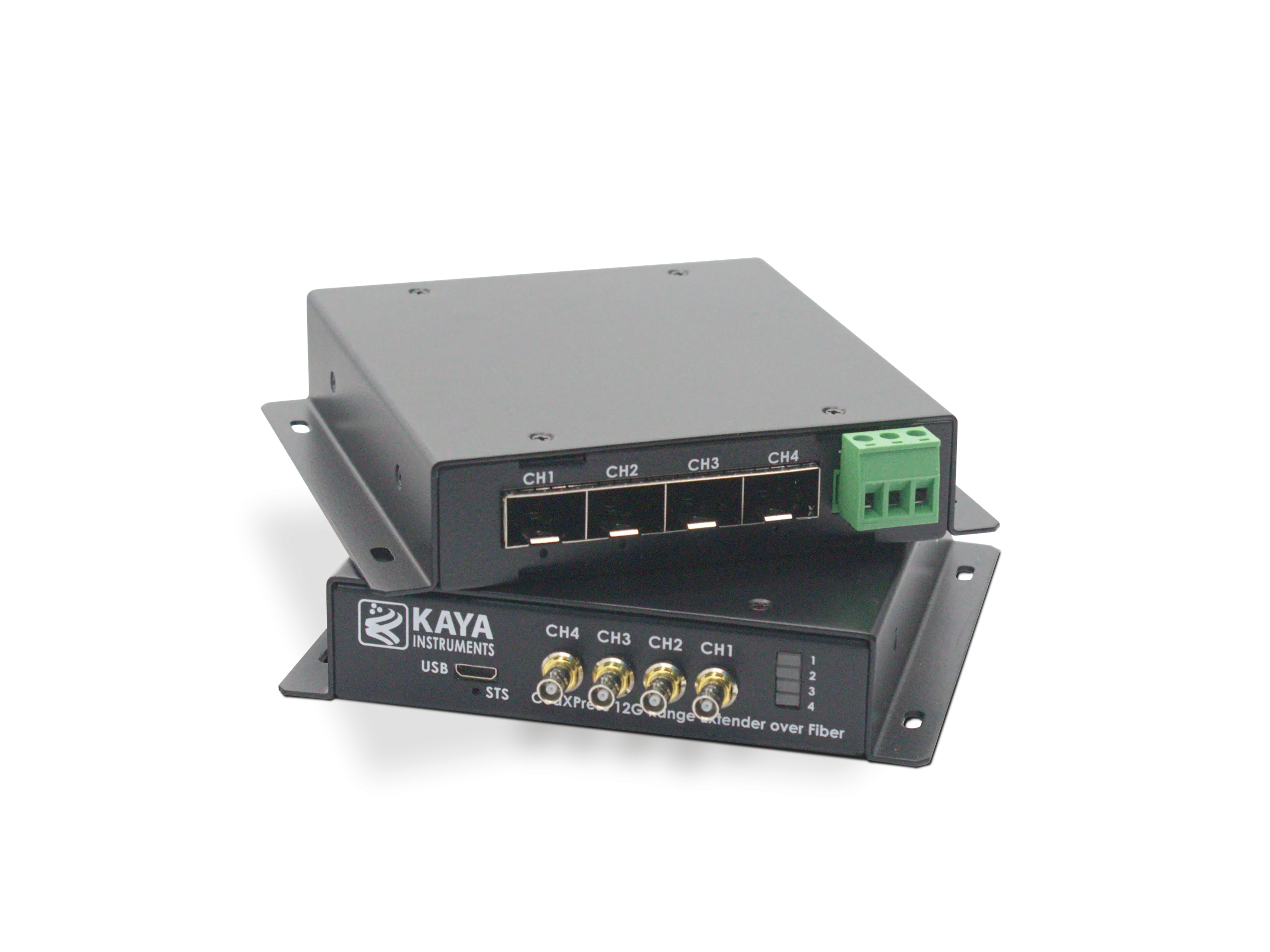
CoaXPress v2.1 Range Extender over Fiber (SFP+)
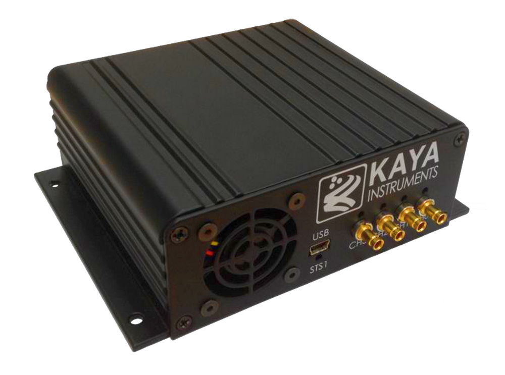
CoaXPress Range Extender over Coax